 Kawasaki J300 - Service manual > Steering
Exploded View


AD: Apply adhesive.
G: Apply grease.
R: Replacement Parts
Special Tools
Head Pipe Outer Race Press Shaft: 57001-1075

Head Pipe Outer Race Remover ID > 37 mm: 57001-1107

Head Pipe Outer Race Driver,  54.5:
57001-1077

Steering Stem Bearing Driver Adapter,  41.5:
57001-1345

Steering Stem Nut Wrench: 57001-1100

Case Assembly Tool,  50.8:
57001-1353

Head Pipe Outer Race Driver,  46.5:
57001-1106

Steering Stem Lock Nut Wrench, 32 mm: 57001-Y014

Steering
Steering Inspection
- Refer to the Steering Play Inspection in the Periodic Maintenance chapter.
Steering Adjustment
- Refer to the Steering Play Adjustment in the Periodic Maintenance chapter.
Steering Stem
Stem, Stem Bearing Removal
- Remove:
Front Forks (see Front Fork Removal in the Suspension chapter)
Upper Handlebar Cover (see Handlebar Cover Removal in the Frame chapter)
Leg Shield Cover (see Leg Shield Removal in the Frame chapter) - Remove the brake master cylinders with the brake hose installed (see Master Cylinder Removal in the Brake chapter).
- Slide the dust covers [A] and disconnect the connectors [B] to remove
the handlebars.
Left Side [C]
Right Side [D] - Remove the band [E].


- Remove:
Handlebar Mounting Bolt [A] and Nut
Collar [B] - Remove the handlebars [C] from the steering stem with the switch housings installed.

- Remove:
Bolts [A]
Clamp [B]

- Remove the cap [A].

- Remove the steering stem locknut [A] with the steering stem locknut
wrench [B].
Special Tool - Steering Stem Locknut Wrench, 32 mm: 57001-Y014
- Remove the washer.

- Pushing up the stem base [A], and remove the steering stem nut [B].
Special Tool - Steering Stem Nut Wrench [C]: 57001-1100
- Remove the steering stem [D].

- Remove:
Stem Cap [A]
Upper Ball Bearing Inner Race [B]
Upper Ball Bearing [C]

- Remove the bearing outer races from the head pipe.
- Using the head pipe outer race remover [A], and hammer [B] the head pipe outer race remover to drive it out.
Special Tool - Head Pipe Outer Race Remover ID > 37 mm: 57001-1107

- Remove the lower ball bearing [A] from the steering stem.

- Remove the lower bearing inner race [A] (with its grease seal) which is pressed onto the steering stem with a suitable commercially available chisel [B].

Stem, Stem Bearing Installation
- Replace the bearing outer races with new ones.
- Drive them into the head pipe at the same time.
Special Tools -
Head Pipe Outer Race Press Shaft [A]: 57001-1075
Head Pipe Outer Race Driver, 46.5 [B]: 57001-1106
Head Pipe Outer Race Driver, 54.5 [C]: 57001-1077

- Apply grease to the outer races.
- Replace the bearing inner races and grease seal with new ones.
- Apply grease to the grease seal.
- Install the grease seal [A] on the steering stem, and drive the lower ball bearing inner race [B] applied the grease onto the stem.
Special Tools - Case Assembly Tool,  50.8
[C]: 57001-1353 Steering Stem Bearing Driver Adapter,
 41.5 [D]:
57001-1345

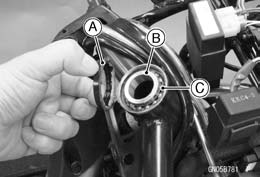
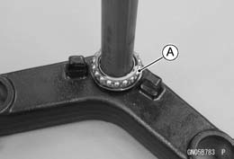
- Apply grease to the lower ball bearing [A], and install it onto the steering stem.
- Apply grease to the upper ball bearing [B] and inner race [C].

- Install:
Upper Ball Bearing [A]
Upper Ball Bearing Inner Race [B]
Stem Cap [C]

- Install:
Steering Stem [A]
Steering Stem Nut [B]
Special Tool - Steering Stem Nut Wrench [C]: 57001-1100

- Settle the bearings in place as follows.
- Tighten the steering stem nut with 51 N*m (5.2 kgf*m, 38 ft*lb) of torque first, and loosen it a fraction of a turn until it turns lightly. Afterward tighten it again with specified torque using a steering stem nut wrench [A].
- Check that there is no play and the steering stem turns smoothly without rattles. If not, the steering stem bearings may be damaged.
Special Tool - Steering Stem Nut Wrench: 57001-1100
Torque - Steering Stem Nut: 20 N*m (2.0 kgf*m, 15 ft*lb)

- Install the washer.
- Install the steering stem locknut [A] with the steering stem locknut wrench [B].
Special Tool - Steering Stem Locknut Wrench, 32 mm: 57001-Y014
Torque - Steering Stem Locknut: 62 N*m (6.3 kgf*m, 46 ft*lb)

- Install the cap [A].

- Replace the handlebar mounting nut [A] with a new one.
- Install:
Handlebars [B]
Collar [C]
Handlebar Mounting Bolt and Nut
Torque - Handlebar Mounting Nut: 44 N*m (4.5 kgf*m, 32 ft*lb)

WARNING If the handlebars do not turn to the steering stop, they may cause an accident resulting in injury or death. Be sure the cables, harnesses and hoses are routed properly and do not interfere with handlebar movement (see Cable, Wire, and Hose Routing section in the Appendix chapter).
- Install the removed parts (see appropriate chapters).
Steering Stem Bearing Lubrication
- Refer to the Steering Stem Bearing Lubrication in the Periodic Maintenance chapter.
Steering Stem Warp Inspection
- Whenever the steering stem is removed, or if the steering can not be
adjusted for smooth action, check the steering stem for straightness.
If the steering stem [A] is bent, replace the steering stem.

Handlebar
Handlebar Removal
- Remove:
Rear View Mirrors [A] (see Rear View Mirror Removal in the Frame chapter)
Handlebar Cover [B] (see Handlebar Cover Removal in the Frame chapter)
Master Cylinders [C] (see Master Cylinder Removal in the Brakes chapter)
Right Switch Housing [D] (see Throttle Cable Removal in the Fuel System (DFI) chapter)
Left Switch Housing [E]
Handlebar Weights [F]
Left Handlebar Grip [G]
Throttle Grip [H]


- Clear the cables, harnesses and hoses from the guide [A].
- Remove:
Handlebar Mounting Bolt [B] and Nut
Collar [C]
Handlebars [D]

Handlebar Installation
WARNING If the handlebars do not turn to the steering stop, they may cause an accident resulting in injury or death. Be sure the cables, harnesses and hoses are routed properly and do not interfere with handlebar movement (see Cable, Wire, and Hose Routing section in the Appendix chapter).
- Replace the handlebar mounting nut with a new one.
- Install the handlebars and collar, and tighten the handlebar mounting bolt and nut.
Torque - Handlebar Mounting Nut: 44 N*m (4.5 kgf*m, 32 ft*lb)
- With a high flash-point solvent, clean off the installation surfaces of the handlebar grip and wipe dry.
- Apply adhesive cement to the inside of the left handlebar grip.
- Install the left handlebar grip, throttle grip and handlebar weights.
- Install the left switch housing.
- Fit the projection [A] of the left switch housing into a hole [B] of the handlebars.
- Install the removed parts (see appropriate chapters).

See also:
 Kawasaki J300 - Service manual > Suspension
Exploded View
 Kawasaki J300 - Service manual > Frame
Exploded View R: Replacement Parts G: Apply grease. Exploded View


