 Kawasaki J300 - Service manual > Throttle Sensor Position and Idle Speed Control Valve Actuator Position
Reset
Kawasaki J300 - Service manual > Throttle Sensor Position and Idle Speed Control Valve Actuator Position
Reset
How to Reset Throttle Sensor Position and Idle Speed Control Valve Actuator Position
The ECU records the throttle sensor position and idle speed control valve actuator position. Therefore, the throttle sensor position and idle speed control valve actuator position have to be reset when throttle body, intake air pressure sensor, idle speed control valve actuator or ECU has been reinstalled.
NOTE
- If close or open the throttle grip randomly, the ECU may record the incorrect the throttle sensor position when the ECU or the throttle body has been reinstalled. It can cause hard to start the engine or idling speed is not smooth when engine installation.
- The idle speed control valve actuator has a motor inside, which controls idle speed control valve actuator to obtain smooth idling speed. The ECU may record the incorrect idle speed control valve actuator position during the engine speed is not working when the ECU or the throttle body has been reinstalled. It can cause engine stop, hard to start the engine or rough idling speed.
Throttle Sensor Position and Idle Speed Control Valve Actuator Position Reset Procedure
1. Place the motorcycle on its center stand.
2. Put the side stand up, and turn the engine stop switch to run position.
3. Turn the ignition switch off.
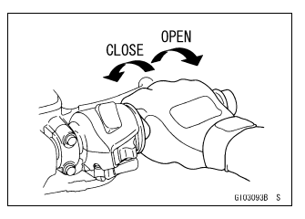
4. Fully open the throttle grip.
5. Turn the ignition switch on.
6. Release the throttle grip after waiting for eight seconds.
7. Turn the ignition switch off.
8. Turn the ignition switch on.
9. The throttle sensor position and idle speed control valve actuator position have been reset successfully.
If the trouble occurs after resetting, repeat the steps from 1 to 8 again.
Throttle Sensor (Service Code 06)
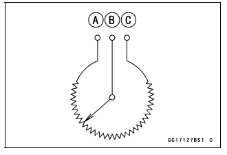
The throttle sensor is a rotating variable resistor that change output voltage according to throttle operating.
The ECU senses this voltage change and determines fuel injection quantity, and ignition timing according to engine rpm, and throttle opening.
Input Terminal [A]: V/R
Output Terminal [B]: V/BK
Ground Terminal [C]: G/P
Throttle Sensor Removal/Adjustment
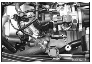
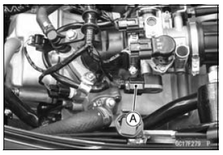
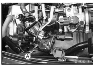
NOTICE Do not remove or adjust the throttle sensor [A] since it has been adjusted and set with precision at the factory.
Never drop the throttle body assy especially on a hard surface. Such a shock to themain throttle sensor can damage it.
Throttle Sensor Input Voltage Inspection
NOTE
- Be sure the battery is fully charged.
- Turn the ignition switch off.
- Remove the storage box (see Storage Box Removal in the Frame chapter).
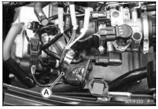
- Disconnect the throttle sensor connector [A].
- Connect the setting adapter [A] between the harness connector and
throttle sensor connector.
Special Tool - Throttle Sensor Setting Adapter: 57001 -1538
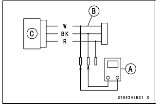
- Connect a digital meter to the setting adapter leads.
Main Throttle Sensor Input Voltage
Connections to Adapter:
Digital Meter (+) ŌåÆ BK (sensor V/R) lead
Digital Meter (-) ŌåÆ W (sensor G/P) lead
- Measure the input voltage with the engine stopped and with the connector joined.
- Turn the ignition switch on.
Input Voltage
Standard: DC 5 V - Turn the ignition switch off.
If the reading is within the standard, check the throttle sensor resistance (see Main Throttle Sensor Resistance Inspection).
If the reading is out of the standard, remove the ECU and check the wiring for continuity between harness connectors.
- Disconnect the ECU and sensor connectors.
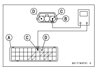
Wiring Continuity Inspection
ECU Connector [A] ŌåÉŌåÆ
Main Throttle Sensor Connector [B]
V/R lead (ECU terminal 6) [C]
G/P lead (ECU terminal 4) [D]
If the wiring is good, check the ECU for its ground and power supply (see ECU Power Supply Inspection).
If the ground and power supply are good, replace the ECU (see ECU Removal/Installation).
- Reset the throttle sensor position (see How to Reset Throttle Sensor Position and Idle Speed Control Valve Actuator Position).
Throttle Sensor Resistance Inspection
- Turn the ignition switch off.
- Measure the throttle sensor resistance in the same way as input voltage
inspection, note the following.
- Disconnect the throttle sensor setting adapter [A] from the connector of the main harness side.
Special Tool - Throttle Sensor Setting Adapter: 57001 -1538
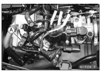
- Connect the setting adapter to the sensor connector only.
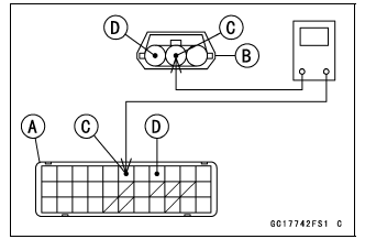
- Connect a digital meter [A] to the setting adapter [B].
Main Throttle Sensor [C]
Main Throttle Sensor Resistance Connections to Adapter: BK (sensor V/R) lead ŌåÉ ŌåÆ W (sensor G/P) lead Standard: 3.5 - 6.5 k╬® @20┬║C (68┬║F)
If the reading is out of the standard, replace the throttle body assy.
If the reading is within the standard, check the output voltage (see Throttle Sensor Output Voltage Inspection).
Throttle Sensor Output Voltage Inspection
- Measure the output voltage at the throttle sensor in the same way as
input voltage inspection, note the following.
- Disconnect the throttle sensor connector and connect the setting adapter [A] between these connectors.
Special Tool - Throttle Sensor Setting Adapter: 57001 -1538
Throttle Sensor Output Voltage
Connections to Adapter:
Digital Meter (+) ŌåÆ R (sensor V/BK) lead
Digital Meter (-) ŌåÆ W (sensor G/P) lead
- Start the engine and warm it up thoroughly.
- Check idle speed to ensure the throttle opening is correct (see Idle Speed Inspection in the Periodic Maintenance chapter).
Idle Speed
Standard: 1 600 +-100 r/min (rpm)
- Turn the ignition switch off.
- Measure the output voltage with the engine stopped, and with the connector joined.
- Turn the ignition switch on.
Output Voltage
Standard:
DC 0.5 - 0.7 V at idle throttle opening
DC 3.5 - 3.8 V at full throttle opening (for reference)
NOTE
- Open the throttle, confirm the output voltage will be raise.
- The standard voltage refers to the value when the voltage reading at the Input Voltage Inspection shows 5 V exactly.
- When the input voltage reading shows other than 5 V, derive a
voltage range as follows.
Example:
In the case of a input voltage of 4.75 V.
0.5 ├Ś 4.75 ├Ę 5.00 = 0.48 V
0.7 ├Ś 4.75 ├Ę 5.00 = 0.67 V
Thus, the valid range is 0.60 - 0.62 V
- Turn the ignition switch off.
If the reading is out of the standard, replace the throttle body assy.
If the reading is within the standard, remove the ECU and check the wiring for continuity between harness connectors.
- Disconnect the ECU and sensor connectors.
Wiring Continuity Inspection
ECU Connector [A] ŌåÉŌåÆ
Main Throttle Sensor Connector [B]
V/BK lead (ECU terminal 5) [C]
G/P lead (ECU terminal 4) [D]
If the wiring is good, check the ECU for its ground and power supply (see ECU Power Supply Inspection).
If the ground and power supply are good, replace the ECU (see ECU Removal/Installation).
- Reset the throttle sensor position (see How to Reset Throttle Sensor Position and Idle Speed Control Valve Actuator Position).
Throttle Sensor Circuit
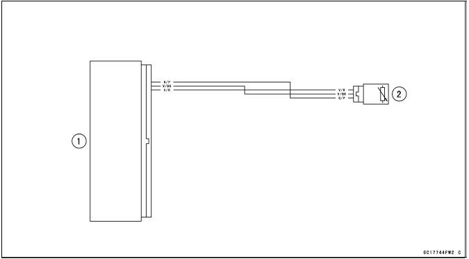
- ECU
- Throttle Sensor
See also:
 Kawasaki J300 - Service manual > How to Read Service Codes
Service codes are shown by a series of long and short blinks of the yellow engine warning indicator light (LED), and the number of two digits on the display, as shown below. When there are a number of problems, all the service codes can be stored and the display will begin starting from the lowest number service code in the numerical order. Then after completing all codes, the display is repeated until ignition switch is turned off. The warning symbol and the number of two digits are displayed at the end of the blinking of the yellow engine warning indicator light (LED). For example, if two problems occurred in the order of 12, 06, the service codes are displayed from the lowest number in the order listed.
Kawasaki J300 - Service manual > Intake Air Pressure Sensor (Service Code 09)
Intake Air Pressure Sensor Removal NOTICE Never drop the intake air pressure sensor especially on a hard surface. Such a shock to the sensor can damage it. Remove the storage box (see Storage Box Removal in the Frame chapter). Disconnect the intake air pressure sensor connector [A]. Remove: Screw [B] Plate [C] Intake Air Pressure Sensor [D]